In this third in our series of posts on IP diagnostics, we’ll discuss analyzing stream timing with a waveform monitor like the Telestream PRISM. As before, the details are covered in our technical guide. This is but a taste of why a Waveform Monitor is a valuable addition to your tool kit and some of the features that PRISM offers.
IP Senders and Receivers
SMPTE standard, 2110-21 characterizes the transmission of video RTP streams from a Sender and regulates the burstiness of the IP packets across the network. At the Receiver, 2110-21 defines a virtual buffer model to regulate the flow of packets and state-specific buffer sizes.
In a perfect world, packets would be produced by a sending device at regular intervals with no gaps. But the rate at which a sender produces these packets is not perfect and will vary based on how the device obtains the video frames and how it converts them to IP packets and sends them on.
There are essentially 2 types of sending devices: Narrow and Wide. There are also 2 flavors of Narrow Senders: Gapped and Linear.
Narrow Senders
A Narrow sender can typically send packets at relatively consistent intervals but will often leave a gap between the end of one image and the beginning of the next. Such a device is sending no packets during this interval and is thus called a “Narrow Gapped sender”. A common example of a Narrow Gapped sender is a gateway card on a camera or other video processing device. There is another “Narrow” device type called a “Narrow Linear sender” which can send out packets with no gap between the end of one field/frame and the next. A common example is a graphics device.
Wide Senders
A Wide Sender is a device that takes longer to process images. The result is a wider variation between packet sends. This may result in the distribution of packets in bursts and is one reason we need buffers at the receiving end.
Networks Inherently Have Latency
Another reason for receiver buffers is that, due to variations across the network, each packet may take a different path from sender to receiver. Even congestion in a switch can delay a packet and cause the same effect. Delays cause out-of-order packets, unacceptably long inter-arrival latency, or burstiness just like a Wide sender does.
Dealing with Latency at the Receiver
To deal with the myriad ways that packets can be delayed and disorganized in a non-deterministic network, ST2110-21 defines a Virtual Receiver Buffer model. Recall, from our previous post, that video and audio anomalies frequently result from buffer over- and underflows. So, understanding Stream Timing diagnostics is crucial.
Analyzing Stream Timing with a Waveform Monitor
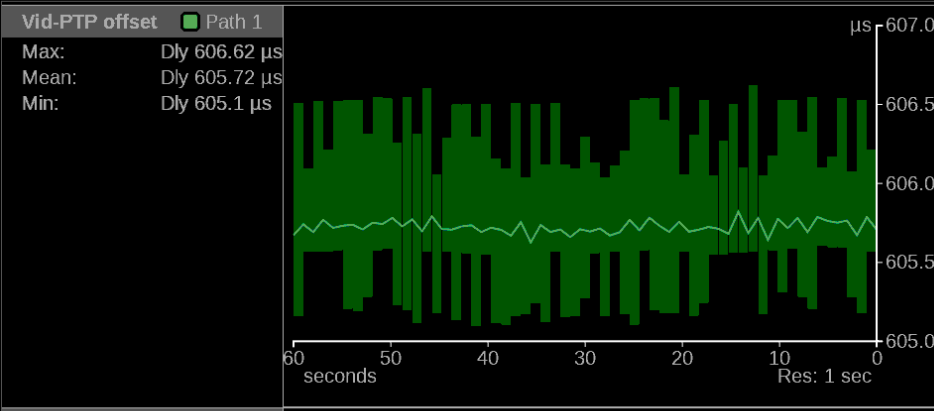
Because stream timing across the network is so critical, PRISM provides more than just the PIT tools we discussed in our last post. (As a reminder, look at the PIT Histogram in the upper right of the following diagram.) The instrument also provides a selection of useful Stream Timing displays. As one example, have a look at the graph of the Vid-PTP Offset on the upper left side of the diagram. Here you can see a plot of the variation of the Timing display measurement as a function of time. This is a valuable way to characterize a Sender’s performance. Below that you can see the Vid-RTP offset. In this case, PRISM derives the current RTP value from the PTP time and compares it to the RTP time extracted from the sender’s packet. This helps to characterize the delay introduced by the network itself.

Of course, none of that matters unless you are locked to PTP in the first place. PRISM lets you validate that with the Timing display which you can see in the lower right.
The technical details behind how one uses these tools to actually identify and resolve issues are the subject of our comprehensive technical guide to diagnosing IP media networks. If you’d like a copy (and who wouldn’t!) you can download it here.
If you’d like to know more about the IP and Stream Timing applications for the PRISM Waveform Monitor check out the PRISM Apps page on the Telestream Website.

